Integration Made Easy with Esco’s Robotic Filling Line Isolator

Introduction
The demand for filling line containment isolation technology continuously increases along with the market growth for aseptic cell therapy and injectables.
Filling line isolators have a wide range of application and serves as a turnkey solution for numerous manufacturing schemes.
Part of the technological advancement in the industry today is providing aseptic containment technology for current processes, and there are projects involving the complex assembly of an isolator technology to house the client’s existing machinery. Other cases though, require the construction of a structure that would support the isolator system with the filling line components.
Sterility, containment, and customization are important parameters in the advancing industry, and Esco’sflexibility in filling line isolator design is the prime solution for a fully integrated client system as it allows easy incorporation of third party equipment.
The Project
Esco engineered a robotic filling line isolator for the safe and accurate filling of potent liquid products in 1 to 10 litre bottles. Capping and weighing of the final products will also be done inside the containment isolator to guarantee a high level of product and operator protection.
Esco ultimately designed a potent filling line isolator which easily incorporated a robotic filling line.
The Filling Process
The filling line isolator system is designed to process sterilised and capped bottles. Once inside the containment technology, the empty bottles will be individually weighed and presented to the cap removal stationvia the robotic arms.
At the filling station, the robotic arm will tilt the bottle at an angle to prevent splashing incidents. The arm was built to withstand the impact of the additional weight of the potent liquid filling the container bottles.
The processed bottles with the refitted caps will then be re-weighed for drug volume confirmation and afterwards conveyed to the final stages of labelling and packaging.
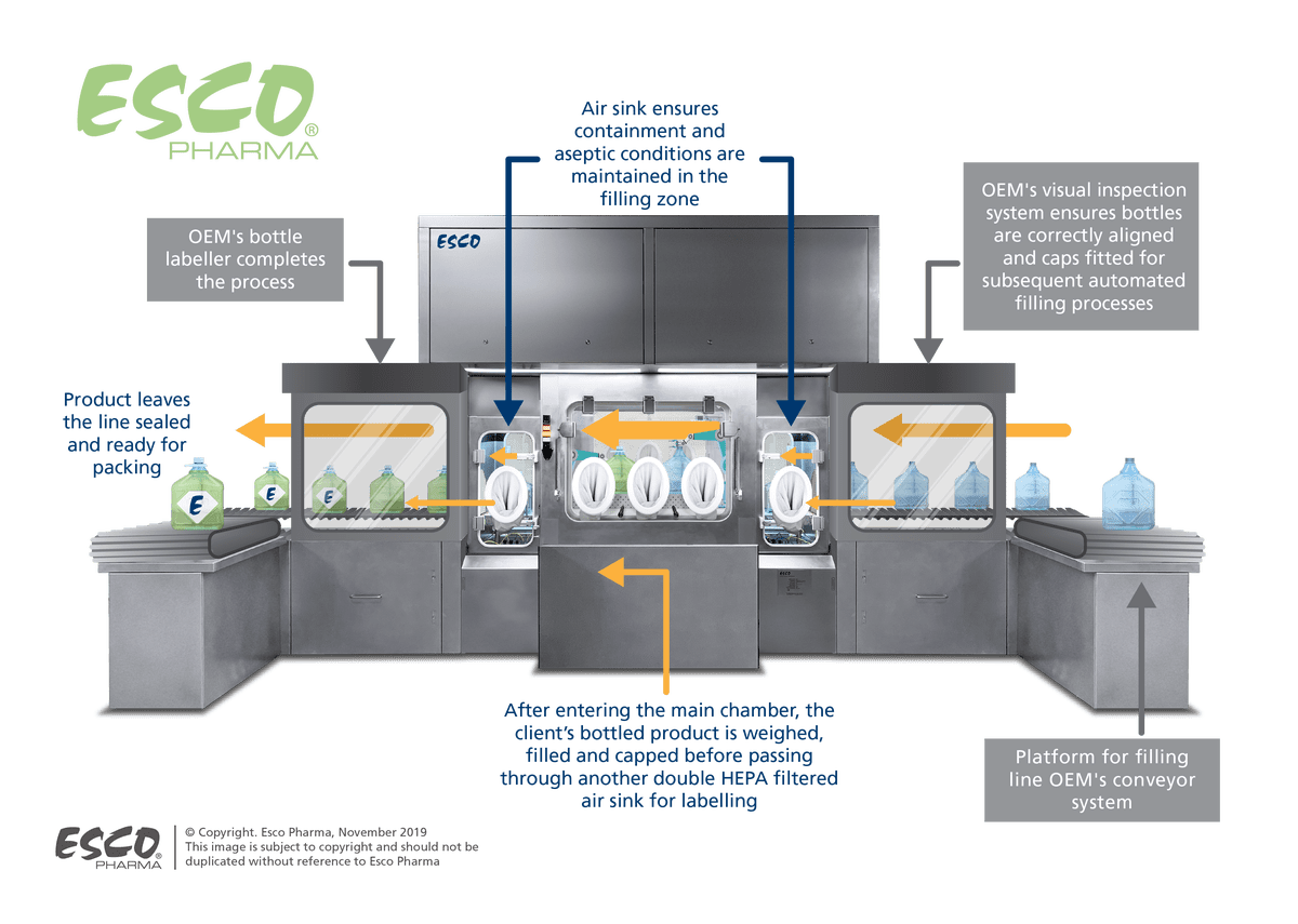
Figure 1. Process flow of the robotic filling line isolator
Project Considerations
To upgrade the client’s current process to an advanced and automated one, complex equipment integrations into the filling line isolator were necessary. Of greater concern is the nature of the final product; in its liquid form, it is not potent but in case of a spillage the liquid can easily dry into its powdered form which then poses a high occupational exposure risk. To remedy this, all worst-case scenarios must be addressed.
Furthermore, the client specified a "one company" appearance for the entire system, so the incorporation of all third party equipment must have a seamless finish. The client’s facility has an internal window which will provide visitors a view of the fully integrated filling line isolator. This allows the company to demonstrate that they are employing cutting-edge technology in their manufacturing process assuring high quality and cost-effectiveness for the final products.
The efficient use of the available space has also been considered in the construction of the filling line isolator system. To guarantee a clean appearance, an all-encompassing design without any remote element is necessary. As such, both the air handling units (AHU) and the main control panel (MCP) were engineered within the footprint of the client’s filling line equipment.
Design Solutions
As with any isolation technology, containment is the main priority of the design. To address the concerns raised by processing large quantities of a potent product, Esco’steam of experts recommended two main design features.
The first recommendation involved a double wall containment system wherein the main process chamber operates under positive pressure while the enclosing walls run at a negative pressure, with integrated HEPA filters at the return point, to ensure contaminant-free return walls. This configuration ensures both key parameters of aseptic conditions and containment will be met.
The second design feature involves the integration of negative pressure air-sinks at the filling chamber inlet and outlet. These will act as the buffer system that assures proper containment of the potent product to prevent cross-contamination risks.
Each sink will also have safe-change double HEPA filters at the return point to remove airborne particulates before the air recirculates back to the surrounding environment.
For the aesthetic continuity of the entire filling line isolator system, Esco ensured that even the polish finish of the isolator to matched the bed plate provided by the original equipment manufacturer (OEM) of the filling line. This design also addressed the client’s requirements for a clean and compact system.
The incorporation of safe change filters, an exhaust fan, and a diffuser into the conveyor system’s support structure further ensured the system’s all-encompassing design (see Figure 1).
The client does not have current requirements for a bio-decontamination system, but the flexibility of Esco’sfilling line isolator design allows for future integration to minimize cost and process-delays.
Project Summary
Filling line isolators are designed to incorporate (OEM) filling line manufacturer’s equipment as standard, however this specific project system design required an entirely different approach in terms of system incorporation.
Although complex, Esco immensely enjoyed working with the client and the filling line’s OEM to create a fully integrated system.
For more information, please visit our page for Filling Line Isolators.
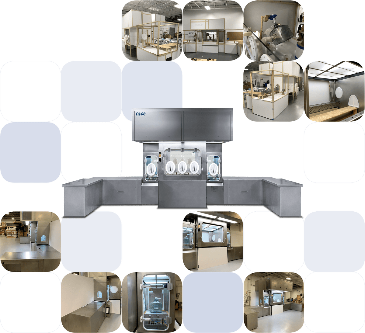
Figure 2. Different stages of equipment development from ergonomic trials to final product.