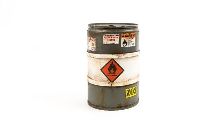
Explosive atmospheres are classified into area classes by ATEX Directive 99/92/EC. This classification is applied to atmospheres where a combination of dusts, aerosols, vapors, gases, and air form an explosive mixture. Examples of areas where this standard must be applied are: oil refineries, paint shops, biogas power plants and peat processing plants.

The ATEX Directive 94/9/EC pertains to the equipment and protection systems intended to be used in explosive atmospheres. In generel, this Directive is called as ATEX Equipment Directive. It is applied to all equipment and components intended to be used in areas where explosive liquids, gases, or dusts are present. For example, the following equipment is classified primarily as primary ATEX equipment: electrical and mechanical equipment, protection systems, safety and control systems, and the components of equipment protection systems. The scope of the Directive does not include medical equipment, household gas equipment or facilities for storing explosives. International standard IEC 60079-0 and the CENELEC EN 60079-0 standard contain more detailed specifications for equipment and requirements.
The main principle behind this safety classification is to prevent the formation of an explosive atmosphere. This is done by eliminating sources of ignition and by minimizing the consequences of possible explosions (94/9/EC). The most important thing is to take all safety requirements into account. These may include all sources of ignition, faults, and potentially incorrect usages. The safety specifications also include safety, maintenance, and protection instructions and related markings.
Common Principles of Explosion and Risk Management
An explosion is a sudden increase in volume and a release of energy in a harmful manner. Usually it involves the generation of high temperatures and the release of gases. An explosion causes pressure waves. Explosions are categorized as deflagrations if these waves are subsonic and detonations if they are supersonic (shock waves). The third type is a thermal explosion, which occurs with the rapid conversion of a highly exothermic reaction accompanied by a temperature rise. The disastrous property of an explosion comes with a rise in pressure and often with a high dose of heat radiation from the fireball, both occurring in a very short period of time. In ATEX areas, causes of explosion must be eliminated or minimized.
To generate the sudden chemical reaction of an oxygen and flammable substance compound, the mixture must be in an explosion range to release a high-energy explosion. Flammable substances normally occur in the form of a dust, mist, gas, or vapor. Normally, an explosion occurs only if the following three main factors react in a convenient mixture:
- Flammable material
- Oxygen
- Ignition source
Flammable materials includes flammable gases, flammable liquids, and flammable solids. Of these, a flammable liquid can occur as a form of mists and also as a vapor. Some of the substances may need only very little energy to react. Normally, gases and vapors are the most flammable. In flammable materials, solids can be in the form of dust, fiber, or flock. The reaction of flammable solids causes a rapid temperature rise and high pressure. Normally solids need more energy to react than gases but the energy of the reaction causes heavy explosions.
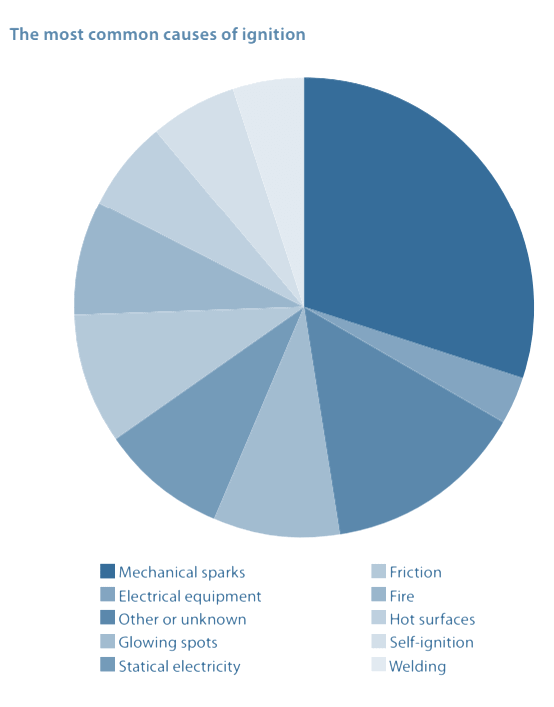
The ignition of an explosion can be started by several sources:
- Hot surfaces
- Flames and hot gases
- Mechanically generated sparks
- Electrical installations
- Equalizing currents
- Static electricity
- Lightning
- Electromagnetic waves
- Optical radiation
- Ionizing radiation
- Ultrasound
- Adiabatic compression and shock waves
- Exothermal reactions
Structures must be designed to eliminate all electro-static charges. Generally charges are formed when two materials with different charges come into contact with each other. A larger contact area or greater distance between the surfaces of the materials touching each other increases the likelihood of a charge. Danger of an increasing charge in material increases when the resistivity of the other material decreases.
If the material has a charge, an electro-static discharge may occur. A charge can be discharged in many ways, but the most common ways are spark discharges and brush discharges. Both of these can cause a dangerous ignition, because the energy released can ignite gases and vapors. A spark discharge occurs when the charge between two conductors in different potentials increases to a sufficient level. In brush discharge, energy is released when a charged object is approached by a round conductive object.
These charges can be eliminated effectively by using potential equalization or grounding. Potential equalization refers to the connection of two conductive objects to each other. Grounding refers to the connection of a conductive object to the ground potential. Discharging must be used when the protective structure is used in a space where explosion group IIC gases are present and the thickness of a non-conductive surface layer exceeds 0.2 mm or the surface resistivity exceeds 1 GΩ. In equipment class two it must be ensured that the projection surface area of non-conductive components, such as value plates and stickers, does not exceed 20 cm2. If the non-conductive surface is surrounded by a grounded frame, its surface area can be multiplied by four.
Explosion Groups
The specification contains three explosion groups. These groups are based on the measured ignition capabilities of gases and vapors at a certain temperature. The classification is split into sections I and II, and groups designated A, B, and C. For example, group A contains common alcohols with a low flash temperature and group C contains gaseous hydrogen with a relatively high flash temperature.
|
Classification of Explosion Groups |
||||
|
Temperature Class |
Ignition Temperature |
II A |
II B |
II C |
|
T1 |
> 450 °C |
Acetone Benzene Ethane Methanol Phenol Propane Toulene |
Carbon monoxide |
Hydrogen |
|
T2 |
> 300 – ≤ 450 °C |
Ethyl Amyl acetate Butane Butyl Cyclohexane |
Ethylene |
Acetylene |
|
T3 |
> 200 – ≤ 300 °C |
Petroleum Diesel fuel Jet fuel Hexane |
Butyl acrylate Ethylene glycol |
|
|
T4 |
> 135 – ≤ 200 °C |
Acetaldehyde |
Ethyl ether |
Carbon bisulfide |
|
T5 |
> 100 – ≤ 135 °C |
|||
|
T6 |
> 85 – ≤100 °C |
|||
Classification of Zones
Area classes are divided into two categories based on the material type. The categories are air/gas mixtures, vapor, particles and air/dust mixtures. Area classifications clarify the protection principles and levels for areas specified in the explosion protection document. This ensures correct selection of the protection principle and maintains cost-efficiency.
Dust atmospheres
Dust atmospheres, in accordance with IEC 60079-10-2 and IEC 60079-31, are classified in different zones. IEC 60079 gives guidance on how to identify and classify the areas where hazards from dust can occur. The area classification method evaluates the material’s properties emission sources, dust layers and formation probability of an explosive dust-air mixture.
Zone 20
An area where combustible dust, as a cloud, is present continuously or frequently during normal operation. Areas, such as the inside parts of equipment, e.g. mixers, silos, filters, mills, transfer pipes, and closed conveyors.
Zone 21
An area where combustible dust, as a cloud id likely to occur during normal operation. Areas, such as filling and emptying areas and places where dust accumulates and the probability for formation of an air-dust mixture is high.
Zone 22
An area where combustible dust clouds may occur infrequently and persist for only short periods. Areas such as storage facilities of closed packages, outlet sides of air filters, surroundings of rarely opened equipment. And if the probability for formation of an air-dust mixture is high in abnormal conditions.
Gas atmospheres
Gas atmospheres are classified as follows according to IEC 60079-10-1 and IEC 60079-7.
Zone 0
An area where an explosive mixture of air and flammable gas, vapor, or particles is present continuously, for long periods, or frequently.
Zone 1
An area where the occasional occurrence of an explosive mixture of air and flammable gas, vapor, or particles is less likely.
Zone 2.
An area where the occasional occurrence of an explosive mixture of air and flammable gas, vapor, or particles is not likely but rare and only short-term.
Equipment Category
The Atex equipment groups and their classifications are divided into two groups and normal industrial use in accordance with 94/9/EC Equipment group II is divided into three categories by the equipment directive. Equipment in higher categories can be used in lower categories, but equipment in equipment group II cannot be used in equipment group I.
Equipment category 1
Design and structure of the equipment ensure an extremely high level of safety when the operating conditions specified by the manufacturer are observed. The equipment must be able to ensure sufficient level of safety even in rare fault situations. The equipment must ensure two protection methods independent of each other and safety must be maintained even when two faults are present simultaneously. Equipment in this category are intended to be used in area classes 0 and 20 and Ga and Da.
Equipment category 2
Design and structure of the equipment ensure a high level of safety when the operating conditions specified by the manufacturer are observed. The equipment must be able to ensure a sufficient level of safety during repeated error situations and normal equipment fault situations. Equipment in this category are intended to be used in area classes 1 and 21 and Gb and Db.
Equipment category 3
Design and structure of the equipment ensure a normal level of safety when the operating conditions specified by the manufacturer are observed. The equipment must be able to ensure a sufficient level of safety during normal operation. Often the manufacturer’s declaration of conformity is sufficient and third-party approval is not required. Equipment in this category are intended to be used in area classes 2 and 22, and Gc and Dc.
Equipment Protection Levels (EPL)
IEC 60079-14 specifies an alternative way to describe zones. EPL uses risk evaluation in equipment selection.
|
Zone |
EPL Marking |
|
0 |
Ga |
|
1 |
Ga or Gb |
|
2 |
Ga, Gb, or Gc |
|
20 |
Da |
|
21 |
Da or Db |
|
22 |
Da, Db, or Dc |
Protection Level for Flammable Gases
|
Type of protection |
Code |
Standards |
EPL |
|
Intrinsically safe |
ia |
IEC 60079-11 |
Ga |
|
Encapsulation |
ma |
IEC 60079-18 |
|
|
Two independent types of protection, each meeting EPL Gb |
|
IEC 60079-26 |
|
|
Flameproof enclosures |
d |
IEC 60079-1 |
Gb |
|
Increased safe |
E |
IEC 60079-11 |
|
|
Intrinsically safe |
Ib |
IEC 60079-7 |
|
|
Encapsulation |
mb |
IEC 60079-11 |
|
|
Oil immersion |
o |
IEC 60079-6 |
|
|
Pressurized enclosures |
p |
IEC 60079-26 |
|
|
Powder filling |
q |
IEC 60079-5 |
|
|
Intrinsically safe |
ic |
IEC 60079-11 |
Gc |
|
Encapsulation |
mc |
IEC 60079-18 |
|
|
Non-sparking |
N |
IEC 60079-15 |
|
|
Restricted breathing |
nR |
IEC 60079-15 |
|
|
Energy limitation |
nL |
IEC 60079-15 |
|
|
Sparking equipment |
nC |
IEC 60079-2 |
Protection Level for Flammable Dusts
|
Type of protection |
Code |
Standards |
EPL |
|
Intrinsically safe |
id |
IEC 60079-11 |
Da |
|
Encapsulation |
mD |
IEC 60079-18 |
|
|
Increased safety |
tD |
IEC 60079-31 |
|
|
Intrinsically safe |
iD |
IEC 60079-11 |
Db |
|
Encapsulation |
mD |
IEC 60079-18 |
|
|
Increased safety |
tD |
IEC 60079-31 |
|
|
Pressurized enclosures |
pD |
IEC 60079-4 |
|
|
Intrinsically safe |
iD |
IEC 60079-11 |
Dc |
|
Encapsulation |
mD |
IEC 60079-18 |
|
|
Increased safety |
tD |
IEC 60079-31 |
|
|
Pressurized enclosures |
pD |
IEC 60079-4 |
Temperature
Temperature groups of flammability groups refer to temperature which the equipment of protective structure surface must not reach any conditions. This temperature limit prevents the gas or vapor flash temperature from being reached. The temperature group and highest allowable surface temperature are usually determined by combined testing of the protective structure and the component.
Temperature class and maximum surface temperature
As per IEC 60079-0, the temperature class specifies how high the surface temperature can rise without the gas, vapor, mist, or dust reaching its flash point and exploding. The relation between the surface temperature and the distance between the heat source and the protective structure is normally linear. This assumption cannot be relied on in all cases, so the surface temperature must be determined by tests and the temperature group selected accordingly. The flash temperature of gases and vapors is generally known to a high degree of accuracy.
|
Temperature class |
Ignition temperature |
Permissible surface temperature of the electrical equipment |
|
T1 |
> 450 °C |
450 °C |
|
T2 |
> 300 – ≤ 450 °C |
300 °C |
|
T3 |
> 200 – ≤ 300 °C |
200 °C |
|
T4 |
> 135 – ≤ 200 °C |
135 °C |
|
T5 |
> 100 – ≤ 135 °C |
100 °C |
|
T6 |
> 85 – ≤100 °C |
85 °C |
A safety factor must be used when calculating the temperature of dust-air mixture and dust layers. For a dust-air mixture, the safety margin is calculated by multiplying the ignition temperature of the mixture by 0.67. When the dust layer thickness exceeds 5 mm, the safety margin is calculated by deducting 75 Kelvin from the maximum tested temperature causing a dust explosion in the atmosphere.
The ignition properties of the dust present must be known when evaluating dust atmospheres. T.ign-cl is the lowest surface temperature required to ignite a dust cloud. T.ign-lay is the lowest surface temperature required to ignite a dust layer and E.min is the lowest electric spark energy capable of igniting the most flammable dust-air mixture.
Examples of the ignition properties of dusts
|
Substance |
T.ign-cl |
T.ign-lay |
E.min |
|
Wood |
≥ 410 °C |
≥ 200 °C |
≥ 100 mJ |
|
Flour |
≥ 380 °C |
≥ 300 °C |
≥ 30 mJ |
|
Brown coal |
≥ 380 °C |
≥ 225 °C |
- |
|
Hard coal |
≥ 500 °C |
≥ 240 °C |
≥ 1000 mJ |
|
Aluminum |
≥ 560 °C |
≥ 340 °C |
≥ 5 mJ |
|
Sulfur |
≥ 240 °C |
≥ 250 °C |
≥ 10 mJ |
Types of protection
Ex d
Ex d protection type refers to a protection type, which withstands the explosion pressure. The protection type must be in accordance with standard IEC/EN 60079-1, which makes it suitable for Zones 1 and 2. Spark-generating components, such as relays and switches, can be installed inside the enclosure. Enclosure protection is based on suffocating the explosion inside the enclosure through grooves in the enclosure so that flammable material is not released outside. The enclosure is always manufactured of metal and only metallic Ex d approved cable glands can be used.
Typical uses are Ex d motors, switch parts of safety switches, switch parts of control switches, Ex heaters, Ex connection boxes, and Ex lighting fixtures.
The enclosure can be repaired if the protection properties do not change and if the enclosure withstands the over-pressure test after the repair. The seal materials must not be made in enclosure.
Ex e
Ex e protection type refers to an increased safety protection type. The protection type must be in accordance with standard IEC/EN 60079-7, making it suitable for Zones 1 and 2. Only intrinsically safe Ex approved components are allowed to be installed inside the enclosure. Suitability of this structure for the area class must be ensured through electrical design and technical solutions so that the equipment does not produce sparks and cannot overheat exceeding the temperature limits. An Ex e enclosure can be manufactured of either metal or plastic. Ex e or Ex d approved cable glands can be used in these enclosures.
Typical uses are Ex e motors, safety and control enclosures, Ex terminal blocks, Ex terminal block enclosures, enclosure parts of Ex lighting fixtures and Ex e bushes and sealing plugs.
The enclosure can be repaired if the sealing class and the temperature class do not change because of e.g. painting.
Ex i
Ex I protection type refers to an intrinsically safe protection type. The protection type must be in accordance with standard IEC/EN 60079-11, making it suitable for area classes 0, 1, and 2. The equipment’s electrical circuit energy must be below the dangerous minimum ignition energy (MIE) even in fault situations. In this case the power is restricted before it is transferred to the Ex area. Sparks are not generated even in short-circuit situations. It is recommended that Ex i enclosures are visually different from normal enclosures. Additionally the circuits should be color-coded and visually different from the other electrical circuits.
Typically, Ex I equipment is used in automation systems. However, it is not suitable for large powers.
Protection class must not change when Ex I equipment is repaired. Also the surface and the air gaps must remain unchanged. Use of reserve fuses with the same value as the ones is allowed in the equipment. Diode barriers must not be repaired but they must be replaced. Internal wiring must not be modifies. Operation of the structure must be ensured after servicing by performing a one-minute voltage test with 500 V.
Ex t
Ex t protection type refers to a dust-proof enclosure. The protection type must be in accordance with standard IEC/EN 60079-31, making it suitable for area classes 0, 1, and 2. Spark-generating components, such as relays and switches, can be installed inside the enclosure. These components do not need to be approved for Ex areas. The protection type must prevent harmful amounts of dust from entering the enclosure. Entry of dust can also be completely prevented.
Typically, Ex tD equipment is used in many industrial applications, such as control and automation systems, and it is possible that some surfaces become hot.
The condition of enclosure seals must be inspected when repairing Ex t equipment. If a seal is damaged, the seal must be changed to a new original spare part manufactured of the same material. Enclosure shock resistance must not deteriorate. Distances of fixed parts must not change in repairs. If the item being repaired is a lighting fixture, all parts used must be approved by the manufacturer and the maximum power must not be exceeded.
Reference:
Ensto. (2011). Basics of Atex. Retrieved from: https://www.slideshare.net/amirin_king/basics-of-atex